Sixth Order Elliptic Band Reject Filter
Requirements
Make an elliptic rejection filter for 1khz, 6pole (plus zeros) with -40dB as +/- 1.5% of 1khz.
Synthesis of Detailed Requirements
The detailed requirements given in Table 1 are synthesized from the requirement statement.
Table 1: Detailed Requirements
| Parameter | Value | Unit | Parameter Description |
|---|---|---|---|
| $f_0$ | 1000 | Hz | Center Frequency |
| PRW | 0.5 (assumed) | dB | Pass Band Ripple Width |
| K | 1 (assumed) | - | Pass Band Gain |
| BW | 133.32 (assumed) | Hz | Band Width |
| f1 | 985 | Hz | Lower stop band edge frequency |
| f2 | 1015 | Hz | Upper stop band edge frequency |
| MSL | 40 | dB | Minimum Stop band attenuation |
Filter Topology Selection
The sixth-order elliptic band reject filter implementation employs a Biquad filter topology. This topology choice is driven by two key advantages: first, biquads naturally support the introduction of zeros, which are fundamental to elliptic filter characteristics; second, they offer superior tuning flexibility during implementation.
Design Summary
A biquad band-reject elliptic filter circuit is shown in Figure 1.
Figure 1: Circuit diagram of a second order Biquad filter topology
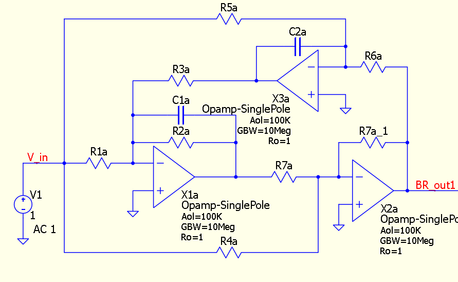
1) This circuit can be used to design a second order band-reject stage using coefficients of the first-order stage of a higher order low-pass elliptic filter. 2) Two of this circuit can be used to design a fourth order band-reject stage using coefficients of a second-order low-pass elliptic filter. 3) Hence three of this circuit can be used to design a sixth order band-reject filter using coefficients of a third-order low-pass elliptic filter 4) Similarly an nth order band-reject elliptic filter can be constructred from the coefficients of a (n/2) order low-pass elliptic filter
Step 1
Table 2 provides the normalized coefficients for a third-order low-pass elliptic filter characterized by 0.5 dB passband ripple width (PRW) and 40 dB minimum stopband attenuation (MSL) (ref. page 191 of the book “A Handbook of Active Filters” by D.E. Johnson, J.R. Johnson, and H.P. Moore.)
Table 2: coefficients for a third-order low-pass elliptic filter with 0.5dB PRW and 40 dB MSL
| MSL | TW | A | B | C |
|---|---|---|---|---|
| 40 | 1.7115 | 9.629215 | 0.580638 | 1.146209 |
| 0.659093 |
The filter coefficients A, B, and C in the first row are for the “second order” stage and the filter coefficient C, in the second row is for the “first order” stage of the third-order low-pass elliptic filter.
Step 2
A2, E1 and D1 for First stage and Second stage:
\[Q = \frac{f_o}{BW} = 7.519\] \[\omega_o = 2{\pi}f_o = 6283.185\]Select a standard value of $C_1$ (preferably near $10/f_0$ $\mu$F)
\[C_1 = \frac{10}{f_o} = 10nF\] \[C_2 = C_1 = 10nF\] \[R_7 = \frac{1}{\omega_oC_1} = 15915.49\] \[A_2= 1+ \frac{1}{2AQ^2}(1+\sqrt{1+4AQ^2}) = 1.043900\] \[E_1= \frac{1}{B}\sqrt{\frac{C}{2}[1+4CQ^2+\sqrt{(1+4CQ^2)^2-(2BQ)^2}]} = 29.664657\] \[D_1= \frac{1}{2}[\frac{BE_1}{QC}+(\sqrt{(\frac{BE_1}{QC})^2-4})]= 1.061739\]First Stage
\(\alpha = A_2 = 1.043900\) \(\beta = \frac{D_1}{E_1} = 0.035791\) \(\gamma = D_1^2 = 1.127289\)
\[R_1 = \frac{1}{K\beta\omega_oC_1} = 444674.1\] \[R_2 = KR_1 = 444674.1\] \[R_3 = \frac{1}{\sqrt{\gamma}\omega_oC_1} = 14990\] \[R_4 = \frac{R_7}K = 15915.49\] \[R_5=\frac{\sqrt\gamma}{K\alpha\omega_oC_2} = 16187.47\] \[R_6=\frac{C_1R_3}{C_2} = 14990.03\]Second Stage
\(\alpha = \frac{1}{A_2} = 0.957946\) \(\beta = \frac{1}{D_1E_1} = 0.031750\) \(\gamma = \frac{1}{D_1^2} = 0.887084\)
\[R_1 = \frac{1}{K\beta\omega_oC_1} = 501276.2\] \[R_2 = KR_1 = 501276.2\] \[R_3 = \frac{1}{\sqrt{\gamma}\omega_oC_1} = 16898.09\] \[R_4 = \frac{R_7}K = 15915.49\] \[R_5=\frac{\sqrt\gamma}{K\alpha\omega_oC_2} = 15648.09\] \[R_6=\frac{C_1R_3}{C_2} = 16898.09\]Third Stage
\[\alpha = \gamma = 1\] \[\beta = \frac{1}{CQ} = 0.202277979\] \[R_1 = \frac{1}{K\beta\omega_oC_1} = 78675.4\] \[R_2 = KR_1 = 78675.4\] \[R_3 = \frac{1}{\sqrt{\gamma}\omega_oC_1} = 15915.49\] \[R_4 = \frac{R_7}K = 15915.49\] \[R_5=\frac{\sqrt\gamma}{K\alpha\omega_oC_2} = 15915.49\] \[R_6=\frac{C_1R_3}{C_2} = 15915.49\]Step 3
Select standard values of resistance and capacitances as close as possible to the calculated values and construct the filter
| Ref Des | 1st stage | 2nd stage | 3rd stage | Remarks |
|---|---|---|---|---|
| C1 | 10nF | 10nF | 10nF | |
| C2 | 10nF | 10nF | 10nF | |
| R7 | 16kΩ | 16kΩ | 16kΩ | |
| R1 | 442 kΩ | 499 kΩ | 78.7 kΩ | |
| R2 | 442 kΩ | 499 kΩ | 78.7 kΩ | |
| R3 | 15 kΩ | 16.90 kΩ | 16 kΩ | |
| R4 | 16 kΩ | 16 kΩ | 16 kΩ | |
| R5 | 16.2 kΩ | 15.6 kΩ | 16 kΩ | |
| R6 | 15 kΩ | 16.9 kΩ | 16 kΩ |
Step 4
Fine tune the filter response by adjusting, R2 to change PRW and R3,R4 to change the center frequency of each of the stages.
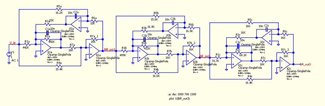
The finetuned 6th order band-reject elliptic filter circuit is shown in Figure 2.
Figure 2: Circuit diagram of a sixth order Biquad Elliptic band-reject filter