13 ft by 20 ft steel Pergola with Clay Tiles Roof
Requirements
Build a projecting roof (pergola) to provide shelter from Sun light and Rain.
Detailed Requirements
Use steel and clay roof tiles remaining from the farm house renovation.
Be able to park a small hatchback car under the Pergola
Available stock of steel
| Material | Stock Qty |
|---|---|
| 0.75 inch by 1.5 inch, 2mm thickness steel rectangular pipes | 22 lengths* |
| 1.5 inch by 2.5 inch, 3mm thickness steel rectangular pipes | 3 lengths |
| 1.5 inch by 2.5 inch, 3mm thickness steel rectangular pipes | 2 nos. of 8ft pieces, 2 nos. of 5 ft and one 4ft piece |
| 3 inch diameter, 4mm thickness pipe | 3 lengths |
| 4 inch by 4 inch, 2mm thickness rectangular pipe | 2 nos. of 6 ft pieces |
| 4 inch by 4 inch, 3mm thickness rectangular pipe | 1 no. of 8 ft piece |
| 6 inch by 6 inch metal plates of 6 mm thickness | 5 |
| 1.06m by 2.6m PUF sheets of 50mm thickness | 5 full pieces and one half piece |
| 8 inch by 12 inch Clay roof tiles | approx. 600 nos. |
- 1 length = 19ft 9 inch is the standard length of steel pipes and angles sold in India.
Initial concept
Provide two pillar posts in the front.
On the rear, instead of erecting pillar posts, use the three protruding 4 inch by 4 inch pipes for support.
Use the 1.5 inch by 2.5 inch pipe for three cross-trusses by inserting them into the open end of the three 4 inch by 4 inch pipe . The cross-truss is inserted at an angle which provides the required height in the front and also makes sure that it touches both the lower and upper sides of the 4 inch by 4 inch pipe for two point support.
Since only two pillar posts are present in the front, make trellis truss structure for the front beam.
Hang a small truss made from 0.75 inch by 1.5 inch pipes between the left and the center 4 inch protruding pipes to support one additional cross-truss.
Support the roof tiles using 0.75 inch by 1.5 inch pipes with their 1.5 inch side perpendicular to the ground.
Detailed Design
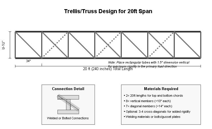
Used Claude sonnet 3.7 to validate the design and get detailed specifications for the front trellis truss structure. Spaced the top and bottom chord 9 inch apart and provided 15 vertical supports and 10 diagonal supports. Provided twice the vertical supports than recommended by Claude since cutting diagonals with an angle less than 45degree was not possible with the chop saw machine.
Personal Protective Equipment:
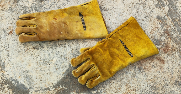
KEEAN Mig/Arc/Tig Welding 16 Inch Gloves With Extra Padded Palm Leather High Temperature Hot Thermal Work Resistant At 500°C Leather Cut Proof Gaunlets With Kevlar Stitching:
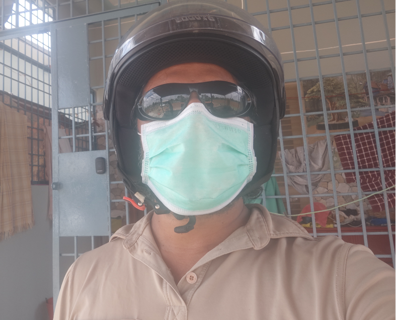
Used generic welding glasses and mask as smoke during welding and cutting is not good. Aditionally used a helmet with front visor for protecting the face from welding and cutting sparks and additional safety.
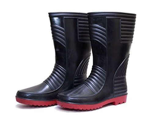
HILLSON Mens Welsafe Safety Gumboots.
Tools:
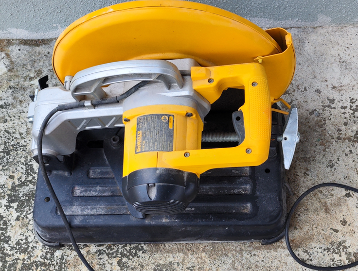
Dewalt DW871 Heavy Duty Chop Saw 355mm 2200W With Soft Start:
iBELL M220-76 Inverter ARC Welding Machine 220A
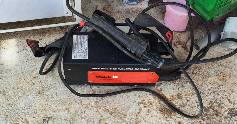
Stock electrode holder and earthing clamp of iBell M220-76 are not good. Hence have replaced it with KEEAN ARC Welding Euro Style Electrode Holder + Heavy Duty Earthing Clamp, Combo, 400 AMP, Without cable wire

IBELL Angle Grinder AG10-72, 1050W Heavy Duty, Copper Armature, Disc dia 100mm, 10500 RPM with Grinding Wheel and Guard

IBELL Rotary Hammer Drill RH26-24, 800W, Copper Armature, SDS Plus Chuck 26mm, 900RPM, Impact Energy 3J, Impact Rate 4000/min, 3 Mode Selector with Forward/Reverse Switch

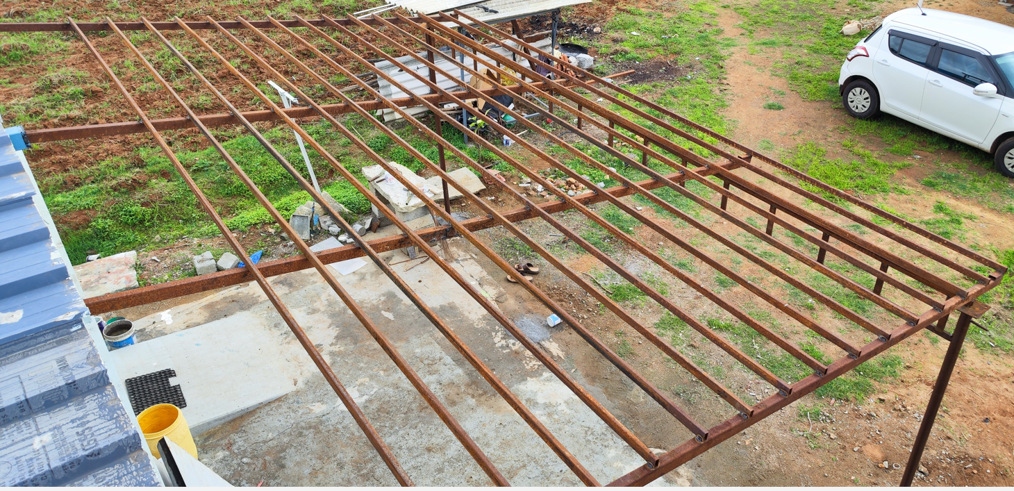
Start of work
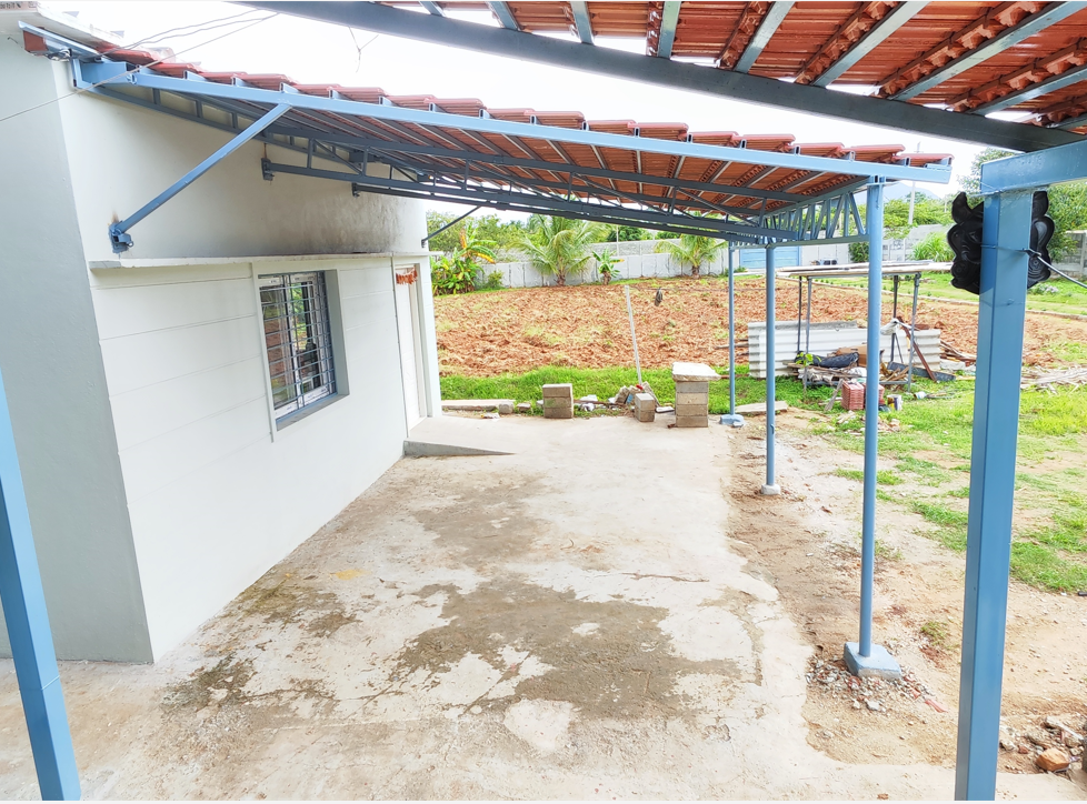
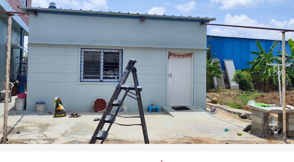
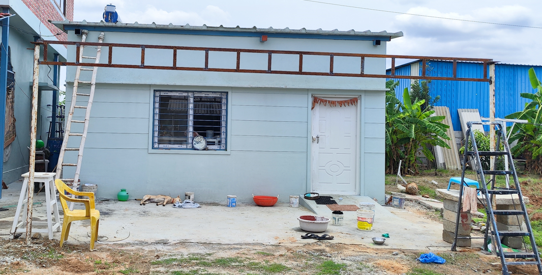
Frontal view of the house for which protruding roof has to be constructed. Image shows the front pillars have been installed:
Fabrication of front trellis truss:
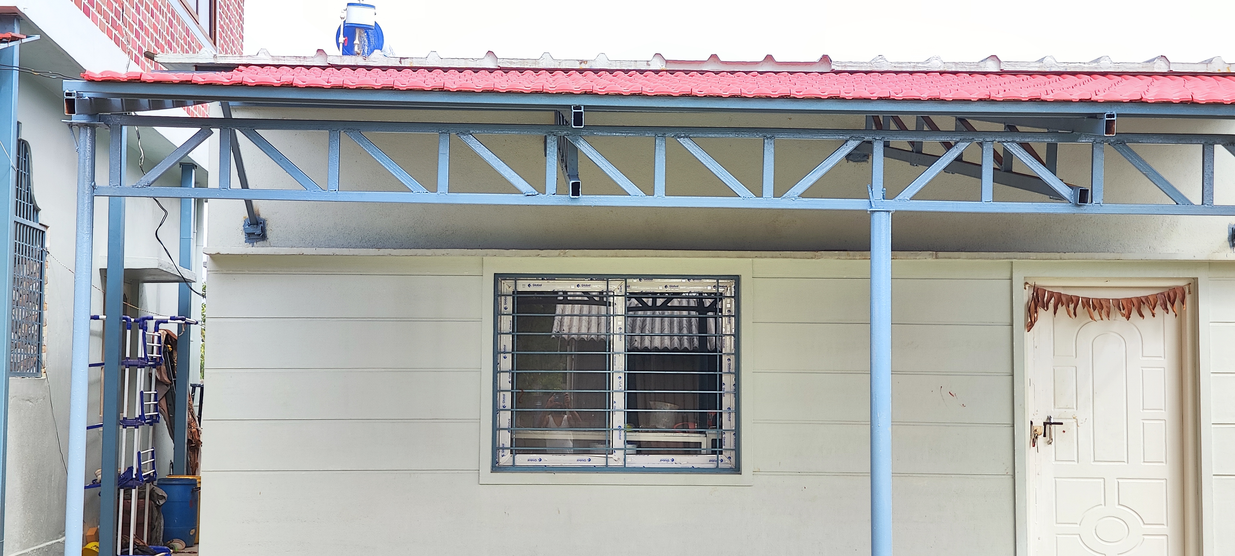
Front main truss:
Initially had only vertical members in the truss!
Cross-trusses (4 nos.)
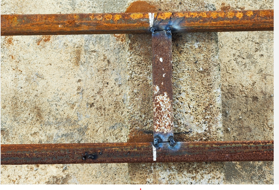
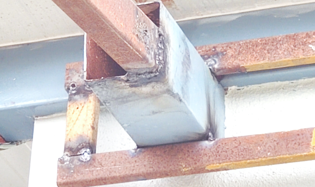
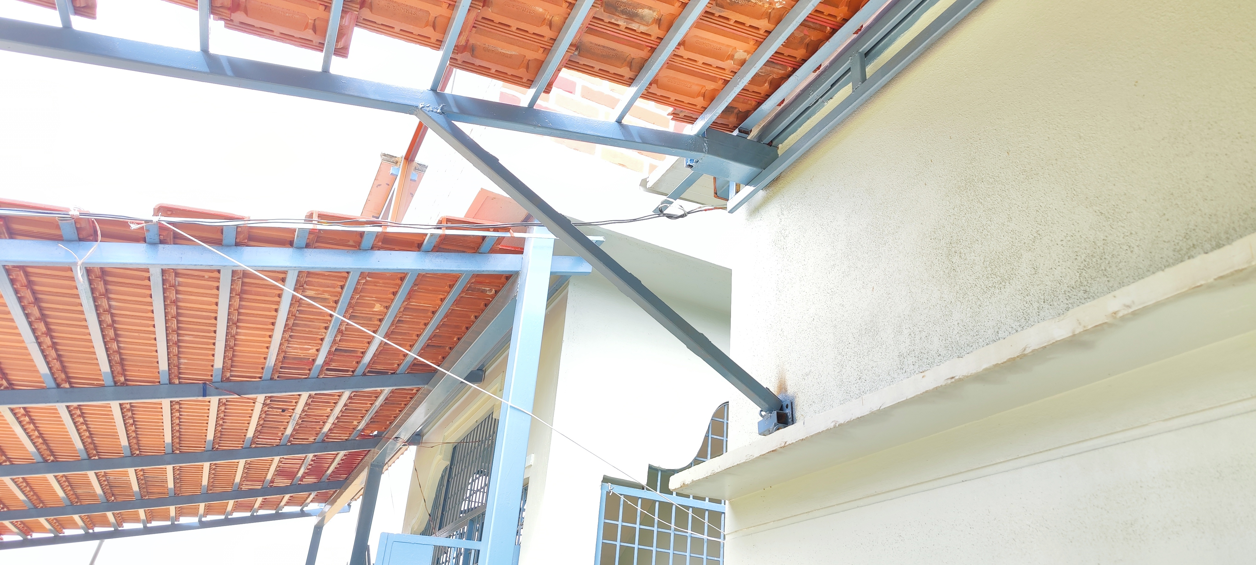
Inserting and Welding of cross-truss 1 to the 4 inch square pipes:
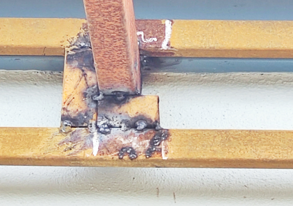
Welding of the cross-truss 2 on the hanging support. Provided a spacer at the bottom to ensure this cross-truss is at the same vertical height as the other three:
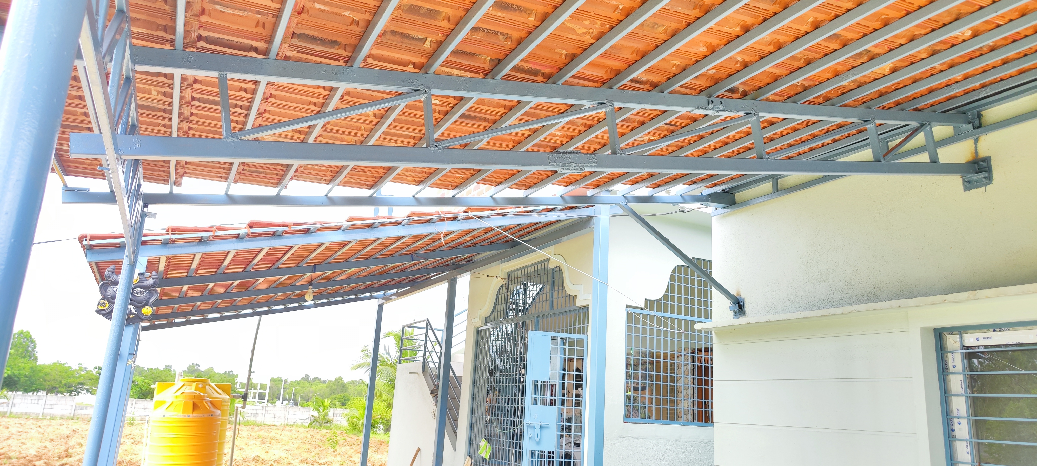
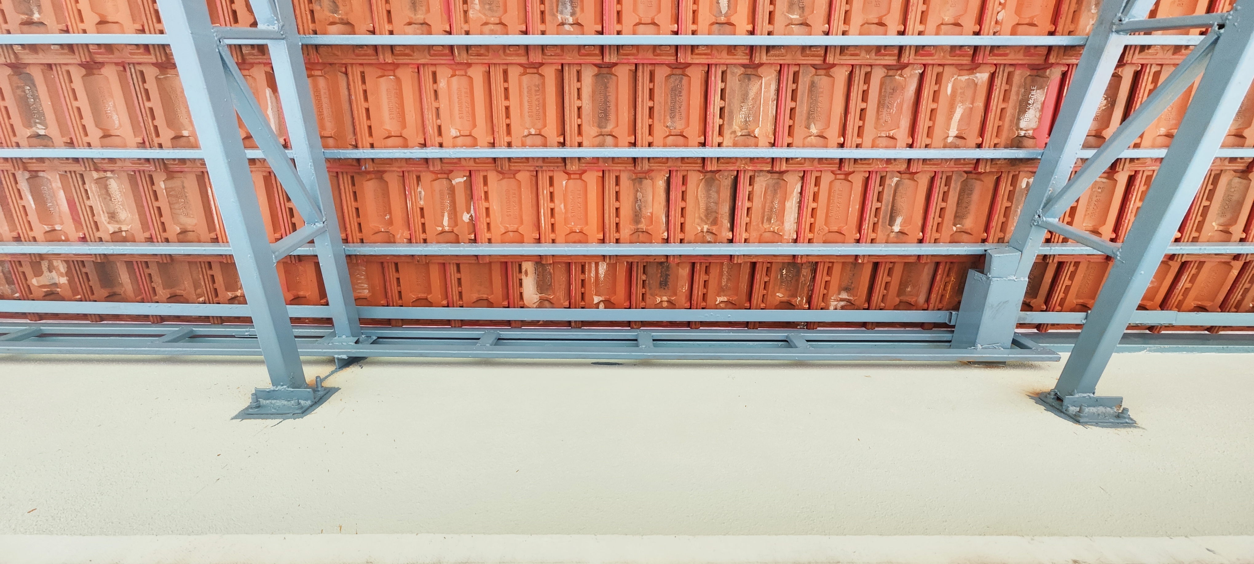
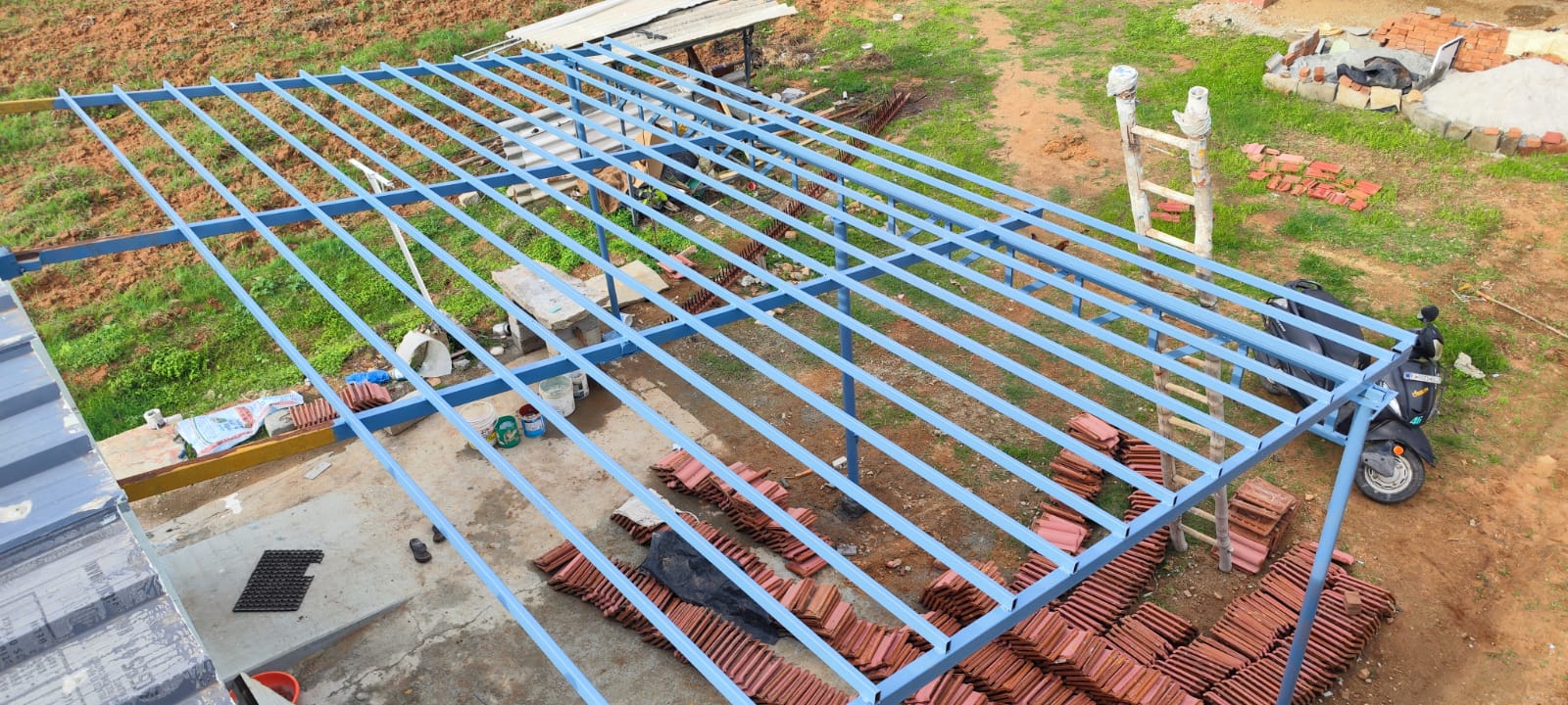
Clay tiles support
Placed the horizontal pipes for supporting clay roof tiles with it’s 1.5 inch side perpendicular to the cross-trusses as strength achieved is multiple times higher than having the 0.75 inch side perpendicular to the beam. This was necessary because typically cross-trusses are spaced 5 ft apart but in this case, they were as high as 7.5ft apart.
Partially completed structure.
Painted the structure with Nippon Smoke grey enamel.
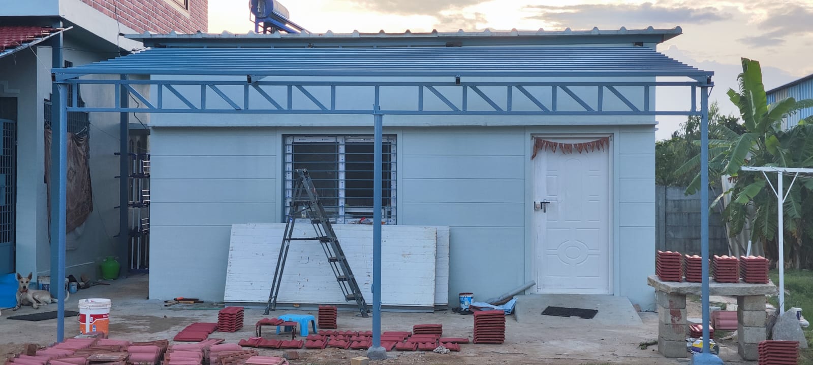
Improving the front truss
Added triangulation to the front truss to make it truly trellis structure. Also added additional pillar post at the center to support front truss as required to handle the 1.2 tonne load of the clay tiles:
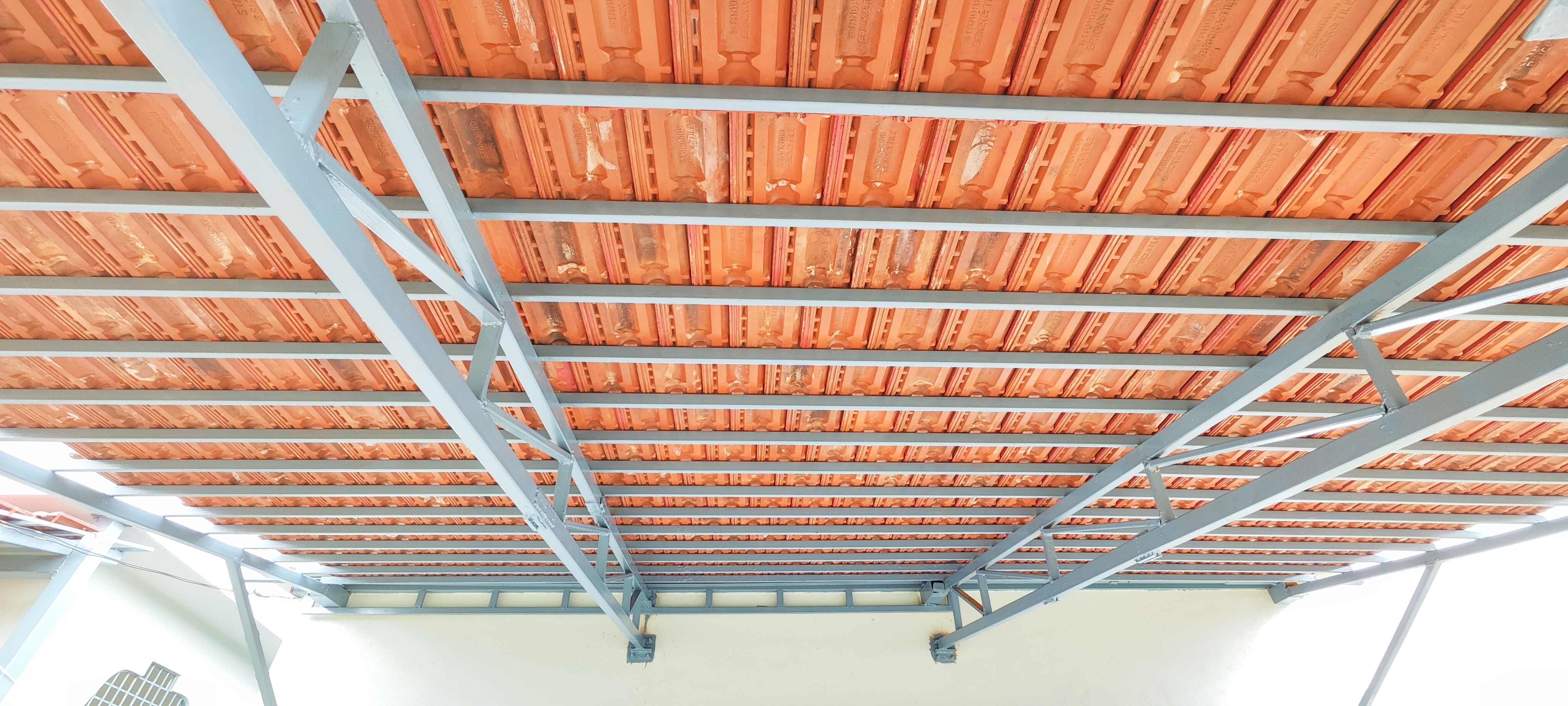
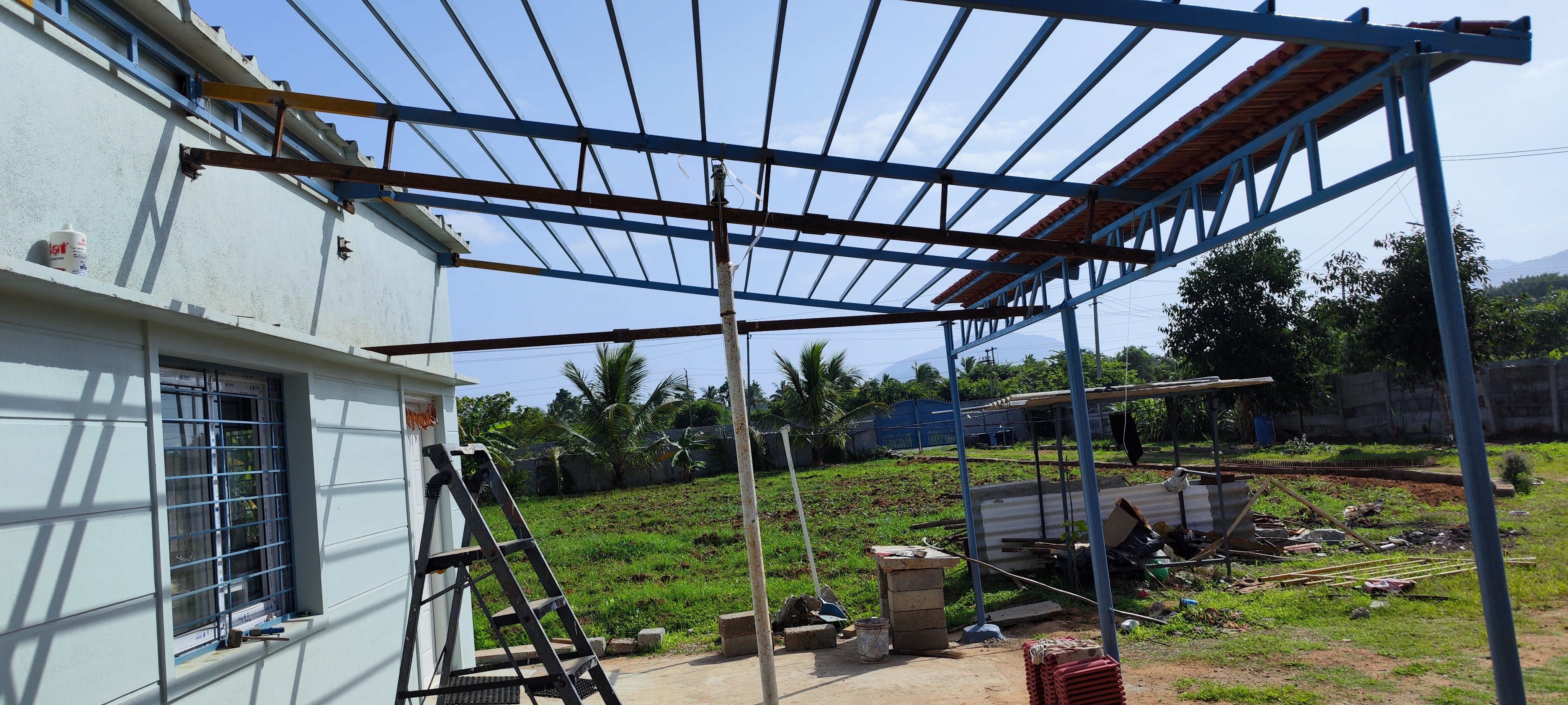
Revaluating the cross-trusses
I felt the four cross trusses running from rear to front made up of 1.5 inch by 2.5 inch were inadequate because conventionally 1.5 inch by 3 inch pipes are used and 5 nos. of cross trusses are used for a span of 20ft and depth of 13 ft.
Using Claude 4, understood that the center two cross-trusses would take 64% of the load. Hence converted them into trellis structure.
Firstly, added a parallel chord 8 inches below the cross-truss. Secondly, to remove the existing deflection on the cross-truss, located a pipe to support the bottom chord and used a car jack to lift the cross-truss and flatten the deflection. Thirdly welded vertical supports between the two chords and fourthly welded the diagonal members.

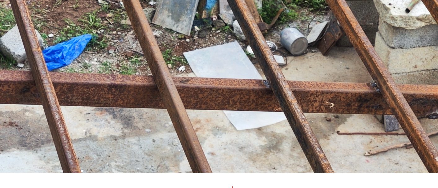
Also reinforced the front trellis truss with additional four diagonals.

After installing 64% roof tiles from the front, the first and the last cross-truss were deflecting by 18mm while Claude AI recommended not to exceed 20mm deflection. Hence added three point support for them using a 1.5 inch by 1.5 inch square pipe of 3 mm thickness.
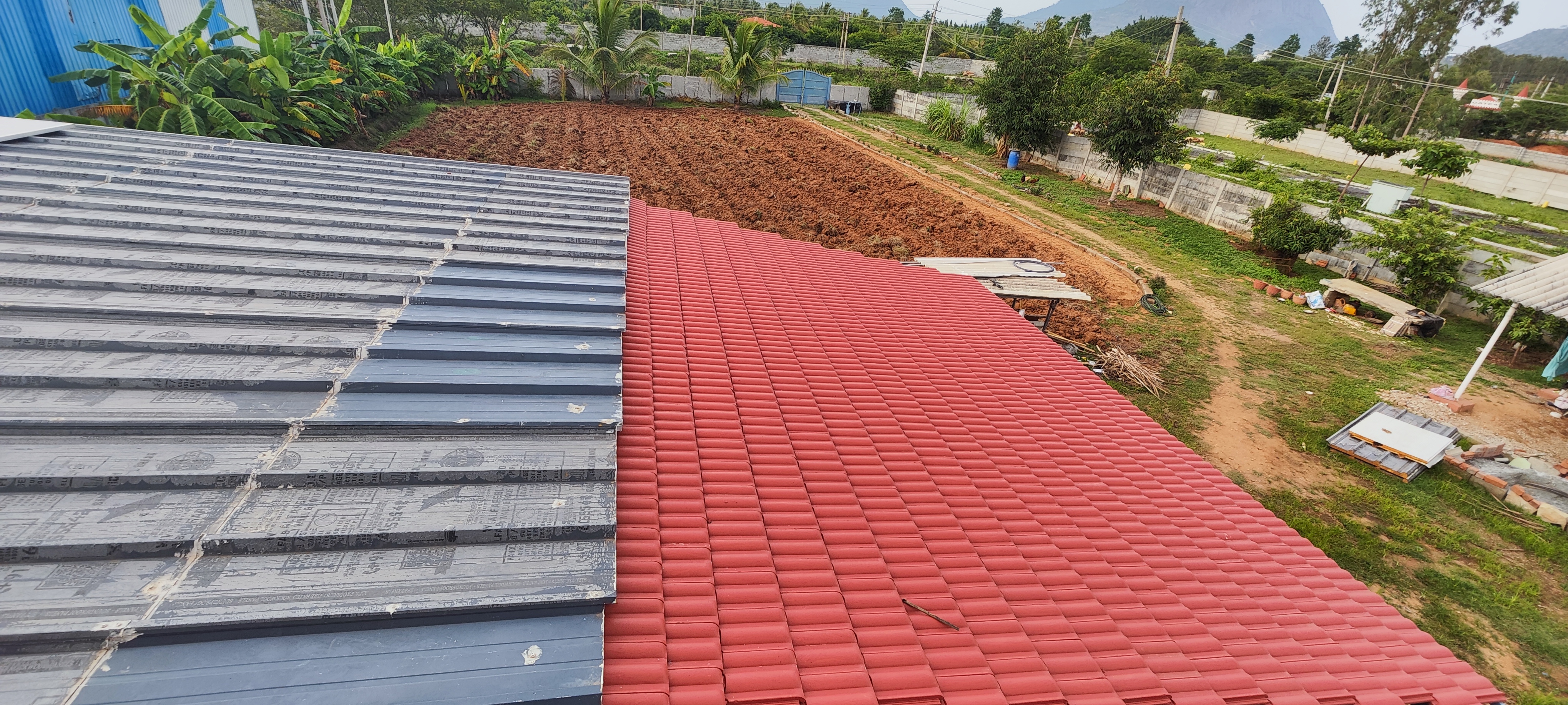
Finally I was confident that the structure can take the 1.2 tonne load of the roof tiles and went ahead covering the remaining portion of the roof.
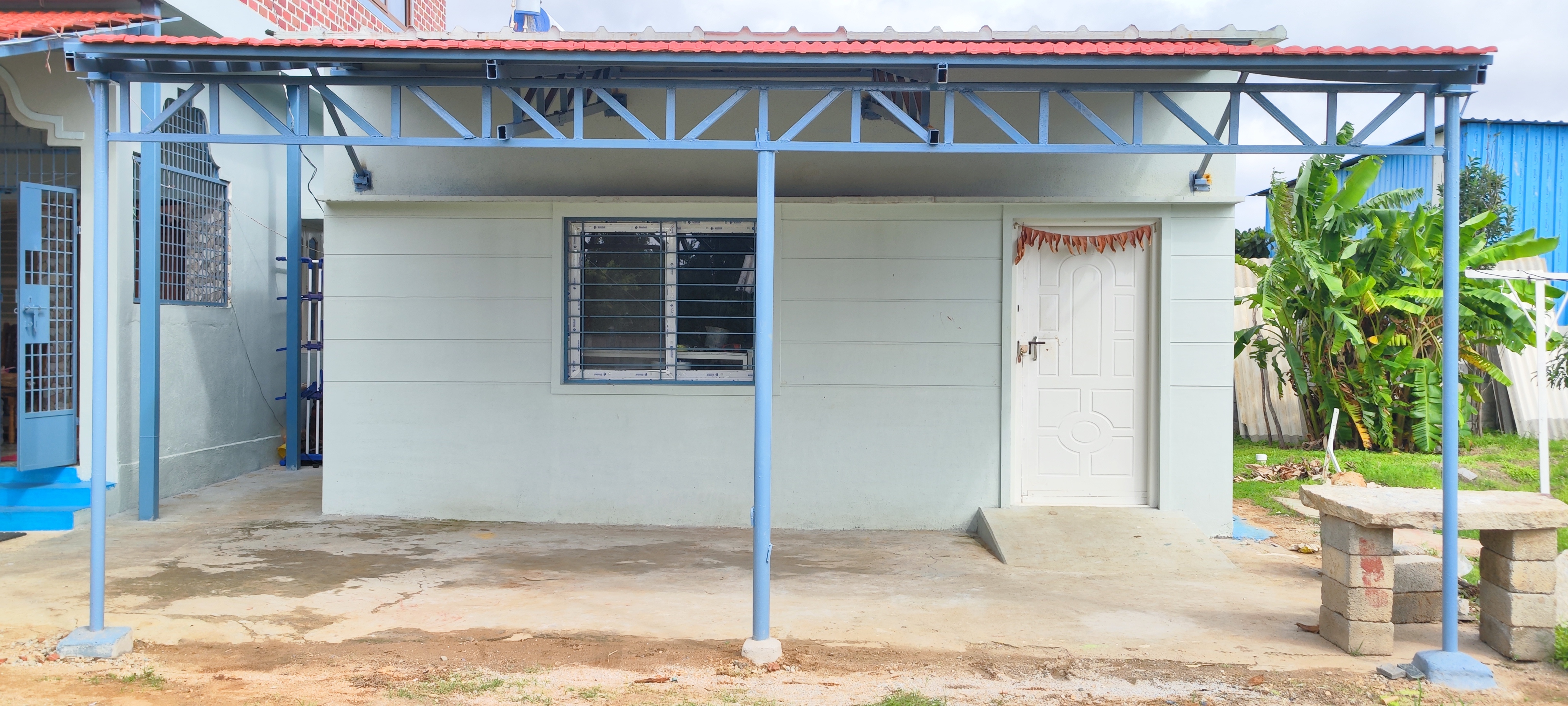
Images of finished Product